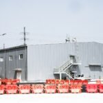

A coolant distribution unit, or CDU, sits between the building water system and the cooling loop inside the racks. Its job is to move heat from the server loop into the building loop without mixing the two.

Most CDUs have a heat exchanger, pumps, a control system, filters, and sensors. The heat exchanger moves heat from the rack coolant to the facility water. The pumps keep flow steady through the racks. Sensors track temperature, pressure, and flow, so the controls can respond when the load changes.
The separation is the reason CDUs matter. The rack coolant is treated and kept clean, and the facility water can be a different quality. If one loop has a problem, the other can be isolated.
Valves are part of every CDU. Control valves adjust flow on the facility side. Isolation valves let a technician service a unit without draining the whole system. Balancing valves set flow across parallel units, so each one gets its share.
When specifying a CDU, engineers look at capacity, approach temperature, pressure drop, and how the unit responds during a power loss. They also look at service access, because a CDU that is hard to maintain becomes a risk over time.
If you follow liquid cooling news, CDUs are a good place to watch. They show how the industry is moving from pilot projects to standard equipment.
Pump selection is a major decision. Pumps must deliver the required flow across the full pressure drop of the rack loop and the heat exchanger. Redundant pumps with automatic switchover keep the loop running if one fails.
Heat exchanger sizing sets the approach temperature. A tighter approach means the rack coolant gets closer to the facility water temperature, which helps performance but may require more surface area and more pumping energy.
Water quality on the facility side must match the CDU’s design. Filters, strainers, and treatment protect the heat exchanger from fouling. Operators log differential pressure across filters to spot clogging early.
Controls need to respond to changes in load. A well-designed CDU adjusts facility flow and pump speed as the rack load changes, so the rack loop stays in range without wasting energy.
Failure modes are part of the design. Engineers look at what happens during a power loss, a pump failure, or a valve stuck closed. The answer should be a controlled state, not a rack that overheats within minutes.
Before a CDU goes into service, its alarms, interlocks, and failover tests should be documented and repeated. A CDU that has been tested once is not the same as one that has been tested under real fault conditions.
Types of CDUs
Liquid-to-liquid CDUs use a heat exchanger to move heat from the rack coolant to the facility water. They are the most common design for large halls because they give a clean separation between the two loops.
Liquid-to-air CDUs reject heat to the room air through a coil. They suit sites with no facility water to connect to, though they put more load back on the room cooling system.
CDUs also come in different scales. In-rack units serve a single rack. In-row units serve a row. Large floor or room units serve many racks. The choice depends on density, redundancy needs, and how the hall will grow.
What happens inside
Pumps pull coolant from the rack return, push it through the heat exchanger, and send it back to the rack supply. A reservoir or expansion tank absorbs changes in fluid volume as the temperature moves.
Control valves on the facility side adjust how much cold water passes through the heat exchanger. The controller watches the rack supply temperature and trims the valve to hold it steady.
Filters protect the cold plates. The tiny channels in a cold plate can clog with particles, so filtration is a serious part of the design. Operators track pressure drop across the filters and change them on a schedule.
A worked example
Here is an illustrative example, not a real site. A CDU serves a row of racks. The rack supply temperature is set to hold steady, and the facility water arrives cooler than that.
When the racks run a heavy workload, return temperature rises. The controller opens the facility valve, so more cold water passes through the heat exchanger and carries away the extra heat. When the load drops, the valve closes down and pump speed may fall.
If one of two pumps fails, the other takes over. Operators get an alarm, but the racks keep running while the pump is repaired.
Redundancy choices
Some sites use paired CDUs so one can serve the load if the other fails. Others use a single large CDU with redundant pumps inside. Paired units give more protection against a heat exchanger leak or a controller problem, but they take more space and cost more.
Questions engineers ask
What is the target approach temperature? It depends on design, but a lower approach needs a larger heat exchanger.
What fluid goes in the rack loop? Often treated water or a water and glycol mix, chosen to match the cold plates and seals.
Who owns maintenance? Usually the facility team, with vendor support for pumps and controllers.
Controls and monitoring
A modern CDU controller does more than hold a temperature. It tracks flow, pressure, and temperature on both loops, calculates heat load, and reports to the building management system. Some also predict maintenance needs from trends in pump power and filter pressure.
Alarm design matters. Operators should get warnings early, such as a slow rise in filter pressure drop, and critical alarms when something needs action. Too many alarms train people to ignore them, so settings should be tuned during commissioning.
Fluid management
The rack loop needs a reliable way to fill, flush, and top off coolant. Many CDUs include a fill port, an air vent, and a sample point. Operators test samples for pH, conductivity, inhibitor level, and particles. Following the manufacturer’s schedule keeps the cold plates from fouling.
Air in the loop is a hidden problem. Trapped air can cause pump cavitation and hot spots. Good designs include vents at high points and a clear procedure for removing air after maintenance.
Planning space and access
CDUs need room for service. Technicians must reach pumps, filters, and valves without moving other equipment. Floor drains, leak trays, and power connections should be planned with the unit. Early coordination between mechanical, electrical, and IT teams avoids rework once equipment arrives.
Testing before service
Before a CDU feeds live racks, the team should test it as a system. Fill and flush the rack loop until the fluid meets the cleanliness target. Run the pumps through their full speed range and confirm flow and pressure against the design. Check the heat exchanger with the facility water running at several temperatures.
Then test faults on purpose. Stop one pump and confirm the standby starts. Close a facility valve and confirm the alarm and response. Cut power and confirm the unit restarts in a safe state. Record each result with the date and the person who witnessed it.
Life cycle and spares
Pumps, filters, gaskets, and sensors wear out. Owners should keep a short list of critical spares on site, such as a spare filter set, a spare pump seal kit, and spare sensors. Planning for these parts early shortens repair times and avoids long waits for a part that would otherwise take down a loop.
A yearly review of CDU data helps too. Pump power, filter pressure drop, and approach temperature trends show which units need attention before they fail. Teams that review the data on a schedule find problems earlier and spend less on emergency repairs.
Coolant distribution unit in practice
When you look at coolant distribution unit, start with the basics and then check how they apply to your own situation. A clear view of coolant distribution unit helps you ask better questions and avoid costly mistakes.
In short, coolant distribution unit is easier to judge when you use plain numbers, trusted sources, and a simple checklist.
Related reading
What a Cooling Tower Does in a Data Center | Reclaimed water data center cooling: what Google does in Georgia | What Is a Hyperscale Data Center and Why Does Power Matter So Much?
For more background, see the U.S. Department of Energy.